GPTI – GROUP OF COMPANIES
-
+971 6 568 2435
-
+971 52 608 5790
An ISO Management system certified company ISO 9001 / ISO 14001 / ISO 45001
An ISO/IEC-17020 Certified Inspection Body. EIAC Certificate No.IB-167
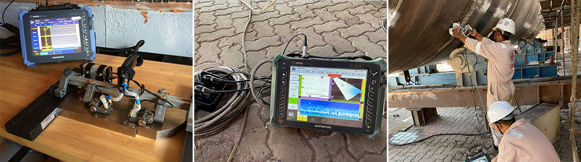
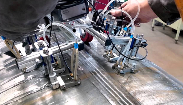
Phased Array Ultrasonic Testing (PAUT), also known as Phased Array UT, is an advanced non-destructive inspection technique that uses a set of Ultrasonic Testing (UT) probes made up of numerous small elements. Phased array systems pulse and receive from multiple elements of an array. These elements are pulsed in such a way as to cause multiple beam components to combine with each other and form a single wave front traveling in the desired direction. Similarly, the receiver function combines the input from multiple elements into a single presentation. Because phasing technology permits electronic beam shaping and steering, it is possible to generate a vast number of different ultrasonic beam profiles from a single probe assembly, and this beam steering can be dynamically programmed to create electronic scans:
| # | Radiography | Automated Ultrasonic Test |
|---|---|---|
| 1 | Extremely hazardous to technicians and general public if used without proper safety measures. | Absolutely no hazard. People can safely work around. |
| 2 | Requires lot of control measures with respect to Radiographer’s health as well as the health concerns of the general public. This is in addition to the general health and safety applicable to all types of industrial work. | No safety control is required except the general occupational health and safety applicable to all type of industrial work. |
| 3 | Radiographic images are two-dimensional C-scan view, which is only a planar view. No idea about depth of flaw can be obtained. | Automated Ultrasonic (Phased Array) testing provide the flaw image in all possible views like top view (C-Scan), side view (B-Scan), end view (D-Scan) in addition to the original A-Scan presentation. These will enhance the ability to interpret, locate and size the flaw image without any inconvenience. |
| 4 | Radiation beam employed is almost unidirectional and sensitive to the flaws, which are parallel or nearly parallel to the beam direction. The formation of image is basically dependant on the differential absorption of radiation in the material. Planer flaws perpendicular or unfavorably oriented to the radiation beam can go undetected. | The ultrasonic sound beam can be applied in various directions simultaneously, thereby increasing the delectability in almost all directions. Formation of image is based on reflection modern computer based analysis gives more precise flaw image. All this contributes to enhanced detect ability and possibility of missing image is almost zero. |
| 5 | Determination of vertical extent (through thickness dimension) of the flaw cannot be estimated. | The use of mechanized UT can provide vertical sizing information, which allows the use of Engineering Critical Assessment (ECA) criteria to be used with mechanized welding. |
| 6 | International and local regulations for the use of radioactive isotopes are very stringent and use of radioisotope is restricted to specific area (heavy wall concrete bunker) and time (night). This eventually decreases production. Moreover, higher thickness material particularly above 60mm poses other problems like very long exposure time, reduced sensitivity and image sharpness. These all factors restrict the use of conventional radioisotopes (IR192) in higher thickness region. | Auto UT can be performed at virtually any time suitable to meet the project requirements. No such safety except general safety is required. Productivity can be increased at a faster rate. It can be used in wide thickness range from 13mm upto 30mm and even more with no reduction in sensitivity and productivity. |
| 7 | Record retention is a big advantage of Radiography, which means the results of examination (Radiographs) can be stored for a specific period of time (typically 3 years) and can be reviewed at any time during this period. | Automated UT relies on microprocessor based technology and like radiography the record of entire joints can be archived for long (no specific time limit) for future review. |
| 8 | A code approved method for testing of welds and other product form for use in pressure vessels, piping and structures. (refer to ASME BPV code, B 31 piping code, AWS D1 structure code, API piping and tank construction code etc. | Recently included as an approved testing method in all the pressure vessel, piping and structural welding codes like ASME BPV code, B 31 pressure piping code, API etc. |
Time of Flight Diffraction (TOFD) method of Ultrasonic Testing is a sensitive and accurate method of Non Destructive Testing method for detecting welds defects. TOFD is a fast and efficient way to scan a lot of weld area in a very short time period. Dead zones near the front and back surface can be enhanced using combined TOFD and Conventional Pulse Echo Techniques. Measuring the amplitude of reflected signal is a relatively unreliable method of sizing defects because the amplitude strongly depends on the orientation of the defect. Instead of amplitude, TOFD uses the time of flight of an ultrasonic pulse to determine the position and size of a reflector. In theory TOFD relies on the information gathered from the diffracted ultrasonic signals impinging on the tips of the defects especially cracks. It is an excellent tools to capture the correct location of a crack especially transverse cracks. With the combination of TOFD and Phased Array a complete weld scan for transverse and horizontal defects can be made easy.